EUR
EUR


Hantek dso8202e 2 Channels 200Mhz Digital Oscilloscope 1GS/s Sample Rate 2M Memory Depth Portable Handheld Osciloscopio
Related Products

-
$ 650.00Add To Cart
$ 650.00


-
$ 180.00Add To Cart
$ 180.00


-
$ 250.00Add To Cart
$ 250.00


-
$ 100.00Add To Cart
$ 100.00


-
$ 70.00Add To Cart
$ 70.00


-
$ 250.00Add To Cart
$ 250.00

Hantek DSO8202E Digital Osciloscopio USB PC Based Storage Lcd Automotive Oscilloscope Portable Multimeter 200Mhz 2 Channels Diagnostic-tool
DSO8000E Series
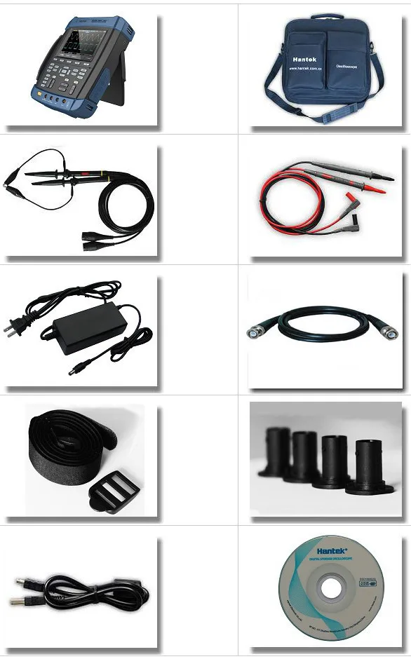
Six in one: Oscilloscope/Recorder/DMM/ Spectrum Analyzer/Frequency Counter/Arbitrary Waveform generator. IP-51 rated for dust, drip and shake proof to withstand harsh environments. Large fuse confirms to European Safety Standard. Battery indicator with easy-changed connect points. Selectable 18650 battery box for matching 18650 battery by yourself. Anti-theft lock hole, tripod fixed hole, hang rope, FLASH light that can be used in darkness. Replaceable BNC safety joints, and additional one set of joints. 1GSa/s sample rate, 2M Memory depth, 6000 counts DMM. Large 5.6 inch TFT Color LCD Display; High Resolution(640*480)

* Six in one: Oscilloscope/Recorder/DMM/ Spectrum Analyzer/Frequency Counter/Arbitrary Waveform generator.
* IP-51 rated for dust, drip and shake proof to withstand harsh environments.
* Large fuse confirms to European Safety Standard.
* Battery indicator with easy-changed connect points. Selectable 18650 battery box for matching 18650 battery by yourself.
* Anti-theft lock hole, tripod fixed hole, hang rope, FLASH light that can be used in darkness.
* Replaceable BNC safety joints, and additional one set of joints.
* High bandwidth 70MHz-200MHz Oscilloscope, 1GSa/s sample rate, 2M Memory depth.
* 25Mz Arb. Waveform Generator, 200 Mesa/s DDS, 12 bit vertical resolution, easy for simulating transducer
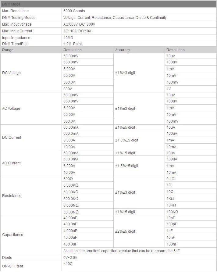
* 6000 Counts DMM, AC/DC voltage, AC/DC current, resistance, break, capacitance, and diode function.
* FFT spectral analysis; Waveform Math: add, subtract, multiply and divide; X-Y mode; more than 20 automatic measurements; PASS/FAIL Check function, apply to engineering application.
* Abundant trigger function, double timebase sampling, easy to observe two waveforms in different frequency.
* Record and replay of more than 1000 waveforms.
* Large 5.6 inch TFT Color LCD Display; High Resolution(640*480)
* USB Host/Device 2.0 full-speed interface; support removable disk; WIFI/LAN Option, easy to control by PC or long-distance.
* Waveform data can be output in WORD,EXCEL, BMP, JPG as time and voltage.

| Model | DSO8072E | DSO8102E | DSO8152E | DSO8202E |
| Acquisition | ||||
| Sample Modes | Real-Time Sample | |||
| Acquisition Modes | ||||
| Normal | Normal data only | |||
| Peak Detect | High-frequency and randon glith capture | |||
| Average | Wavefom Average, selectable 4,8,16,32,64,128 | |||
| Inputs | ||||
| Inputs Coupling | AC, DC, GND | |||
| Inputs Impendance | 1M2% 20pF3pF | |||
| Probe Attenuation | 1X, 10X | |||
| Supported Probe Attenuation Factor | 1X, 10X, 100X, 1000X | |||
| Maximum Input Voltage | CAT I and CAT II: 300VRMS (10×), Installation Category; CAT III: 150VRMS (1×) |
|||
| Horizontal System | ||||
| Sample Rate Range | 1GS/s | |||
| Waveform Interpolation | (sin x)/x | |||
| Record Length | 2M | |||
| SEC/DIV Range | 4ns/div~2000s/div, in a 2, 4, 8 sequence | 2ns/div~2000s/div, in a 2, 4, 8 sequence | ||
| Sample Rate and Delay Time Accuracy |
50ppm over any 1ms time interval | |||
| Scanning Speed Range | 4ns/div to 8ns/div; (-8div x s/div) to 40ms; 20ns/div to 80s/div;(-8div×s/div) to 40ms; 200s/div to 40s/div;(-8div×s/div) to 400s; |
2ns/div to10ns/div;(-4div×s/div) to 20ms; | ||
| Delta Time Measurement Accuracy (Full Bandwidth) |
Single-shot, Normal mode: (1 sample interval +100ppm × reading + 0.6ns); >16 averages: (1 sample interval + 100ppm × reading + 0.4ns); Sample interval = s/div ÷ 200 |
|||
| Vertical System | ||||
| Vertical Resolution | 8-bit resolution, all channel sampled simultaneously | |||
| Volts Range | 2mV/div to 100V/div at input BNC | |||
| Bandwidth | 70MHz | 100MHz | 150MHz | 200MHz |
| Rise Time at BNC( typical) | 5ns | 3.5ns | 2.3ns | 1.8ns |
| Analog Bandwidth in Normal and Average modes at BNC or with probe, DC Coupled |
400V(100V/div-20V/div); 50V(10V/div-5V/div); 40V(2V/div-500mV/div); 2V(200mV/div-50mV/div); 400mV(20mV/div-2mV/div); |
|||
| Math | +, -, *, /, FFT | |||
| FFT | Windows: Hanning, Flatop, Rectamgular, Bartlett, Blackman; 1024 sample point | |||
| Bandwidth Limit | 20MHz | |||
| Low Frequency Response (-3db) | 10Hz at BNC | |||
| DC Gain Accuracy | 3% for Normal or Average acquisition mode, 100V/div to 10mV/div. 4% for Normal or Average acquisition mode, 5mV/div to 2mV/div. |
|||
| DC Measurement Accuracy, Average Acquisition Mode |
Measurement Type: Average of 16 waveforms with vertical position at zero Accuracy: (3% × reading + 0.1div + 1mV) when 10mV/div or greater is selected. Measurement Type: Average of 16 waveforms with vertical position not at zero Accuracy: [3% × (reading + vertical position) + 1% of vertical position + 0.2div]. |
|||
| Volts Measurement Repeatability, Average Acquisition Mode |
Delta volts between any two averages of 16 waveforms acquired under same setup and ambient conditions | |||
| Trigger System | ||||
| Trigger Types | Edge, Video, Pulse, Slope, Over time, Alternative | |||
| Trigger Source | CH1, CH2, AC Line | |||
| Trigger Modes | Auto, Normal, Single | |||
| Coupling Type | DC, AC, HF Reject, LF Reject, Noise Reject | |||
| Trigger Sensitivity (Edge Trigger Type) |
DC(CH1,CH2): 1div from DC to 10MHz; 1.5div from 10MHz to 100MHz; 2div from 100MHz to Full; AC: Attenuates signals below 10Hz ; HF Reject: Attenuates signals above 80kHz; LF Reject: Same as the DC-coupled limits for frequencies above 150kHz; attenuates signals below 150kHz. |
|||
| Trigger Level Range | CH1/CH2: 8 divisions from center of screen; | |||
| Trigger Level Accuracy( typical)Accuracy is for signals having rise and fall times 20ns | CH1/CH2: 0.2div × volts/div within 4 divisions from center of screen; | |||
| Set Level to 50%(typical) | Operates with input signals 50Hz | |||
| Video Trigger | ||||
| Video Trigger Type | CH1, CH2: Peak-to-peak amplitude of 2 divisions; | |||
| Signal Formats and Field Rates | Supports NTSC, PAL and SECAM broadcast systems for any field or any line | |||
| Holdoff Range | 100ns ~ 10s | |||
| Pulse Width Trigger | ||||
| Pulse Width Trigger Mode | Trigger when (< , >, = , or ); Positive pulse or Negative pulse | |||
| Pulse Width Trigger Point | Equal: The oscilloscope triggers when the trailing edge of the pulse crosses the trigger level. Not Equal: If the pulse is narrower than the specified width, the trigger point is the trailing edge. Otherwise, the oscilloscope triggers when a pulse continues longer than the time specified as the Pulse Width. Less than: The trigger point is the trailing edge. Greater than (also called overtime trigger): The oscilloscope triggers when a pulse continues longer than the time specified as the Pulse Width |
|||
| Pulse Width Range | 20ns ~ 10s | |||
| Slope Trigger | ||||
| Slope Trigger Mode | Trigger when (< , > , = , or ); Positive slope or Negative slope | |||
| Slope Trigger Point | Equal: The oscilloscope triggers when the waveform slope is equal to the set slope. Not Equal: The oscilloscope triggers when the waveform slope is not equal to the set slope. Less than: The oscilloscope triggers when the waveform slope is less than the set slope. Greater than: The oscilloscope triggers when the waveform slope is greater than the set slope. |
|||
| Time Range | 20ns ~ 10s | |||
| Overtime Trigger | ||||
| Over Time Modee | Rising edge or Falling edge | |||
| Time Range | 20ns ~ 10s | |||
| Alternative Trigger | ||||
| Trigger on CH1 | Internal Trigger: Edge, Pulse Width, Video, Slope | |||
| Trigger on CH2 | Internal Trigger: Edge, Pulse Width, Video, Slope | |||
| Trigger Frequency Counter | ||||
| Readout Resolution | 6 digits | |||
| Accuracy (typical) | 30ppm (including all frequency reference errors and 1 count errors) | |||
| Frequency Range | AC coupled, from 4Hz minimum to rated bandwidth | |||
| Signal Source | Pulse Width or Edge Trigger modes: all available trigger sources The Frequency Counter measures trigger source at all times, including when the oscilloscope acquisition pauses due to changes in the run status, or acquisition of a single shot event has completed. Pulse Width Trigger mode: The oscilloscope counts pulses of significant magnitude inside the 1s measurement window that qualify as triggerable events, such as narrow pulses in a PWM pulse train if set to < mode and the width is set to a relatively small time. Edge Trigger mode: The oscilloscope counts all edges of sufficient magnitude and correct polarity. Video Trigger mode: The Frequency Counter does not work. |
|||
| Measure | ||||
| Cursor Measurement | Manual: Voltage difference between cursors: V Time difference between cursors: T Reciprocal of T in Hertz (1/T); Tracing: The valtage and time at a waveform point; |
|||
| Auto Measuerment | Frequency, Period, Mean, Pk-Pk, Cycli RMS, Minimum, Maximum, Rise time, Fall Time, +Pulse Width, -Pulse Width, Delay1-2Rise, Delay1-2Fall, +Duty, -Duty, Vbase, Vtop, Vmid, Vamp, Overshoot, Preshoot, Preiod Mean, Preiod RMS, | |||
| Waveform Generator Mode | ||||
| Frenquency Range | 1Hz(DC)~25MHz | |||
| DAC Clock | 2K~200MHz adjustable | |||
| Memory Depth | 4KSa | |||
| Vertical Resolution | 12 Bits | |||
| Stability | <30ppm | |||
| Amplitude | 3.5V Max. | |||
| Output Impedance | 50 | |||
| Output Current | 50mA Ipeak=50mA | |||
| System Bandwidth | 25M | |||
| Harmonic Wave Distortion | -50dBc(1KHz), -40dBc(10KHz) | |||
| General Specifications | ||||
| Display Resolution | 640 horizontal by 480 vertical pixels | |||
| Display Contrast | Adjustable (16 gears) with the progress bar | |||
| Probe Compensator Output | ||||
| Output Voltage( typical) | About 2Vpp into 1M load | |||
| Frequency(typical) | 1kHz | |||
| Power Supply | ||||
| Supply Voltage | AC Input:100-240VACRMS,0.6A MAX,50Hz~60Hz; DC Output:9V,2A | |||
| Power Consumption | <30W | |||
| Environmental | ||||
| Temperature | Operating: 32F to 122F (0C to 50C); Nonoperating: -40F to 159.8F (-40C to +71C) |
|||
| Cooling Method | Convection | |||
| Humidity | +104F or below (+40C or below): 90% relative humidity; 106F to 122F (+41C to 50C): 60% relative humidity |
|||
| Altitude | Operating: Below 3,000m (10,000 feet); Nonoperaring: Below 15,000m(50,000 feet) |
|||
| Mechanical | ||||
| Size | 260mmmm; 220mm; 75mm | |||
| Weight | 2.5KG(without Packing) | |||